The Screen Behind the Mirror
Introduction:
Dr. Evil has contracted your valuable services to build for him the world's most powerful "laser". Of course before you spend one billion dollars building the thing, you want to run some simulations first to make sure everything will work as designed. For this phase of the project, you will be simulating part of the aiming system which uses mirrors and other optics to change the direction of the laser beam.
The simulation consists of a flat square table with mirrors, beam splitters, and beam detectors arranged on the tabletop, and with each object represented by a one dimensional line segment. The list below describes each of the object types in detail:
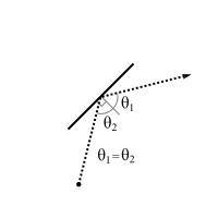
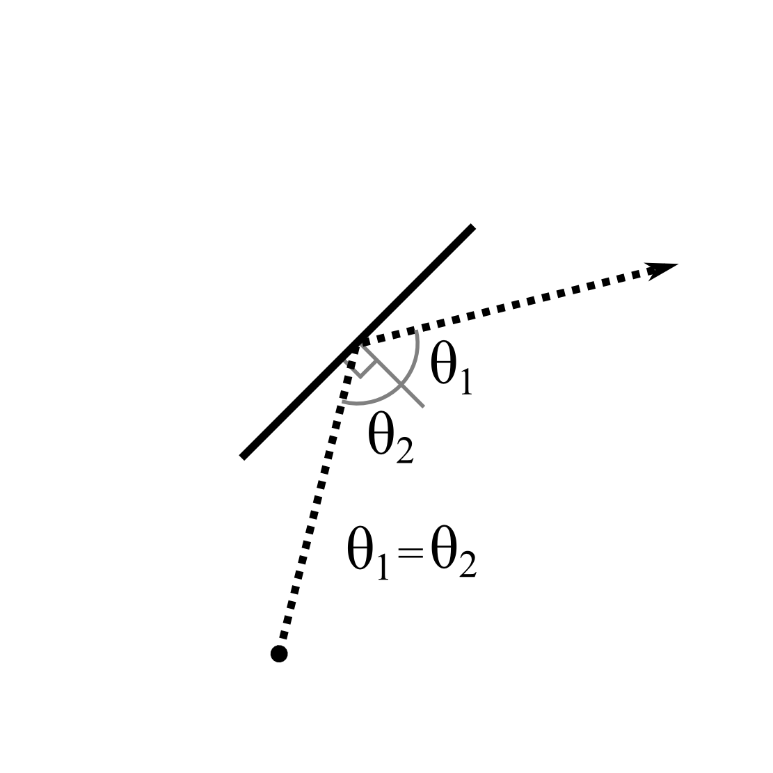
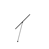
- mirror : A mirror object will reflect any laser beam striking its surface. The reflected beam leaves at the same angle of incidence as the incoming beam. Note that both sides of a mirror object are reflective.
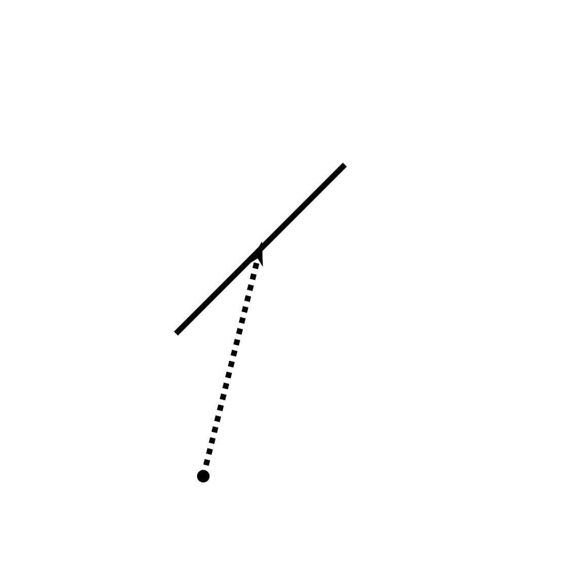
detector : A detector is an opaque object which absorbs any laser beam striking it. The simulation must also keep track of which detectors are struck by a laser for program output purposes. Note that a laser beam strike on either side of a detector counts as a "hit".
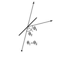
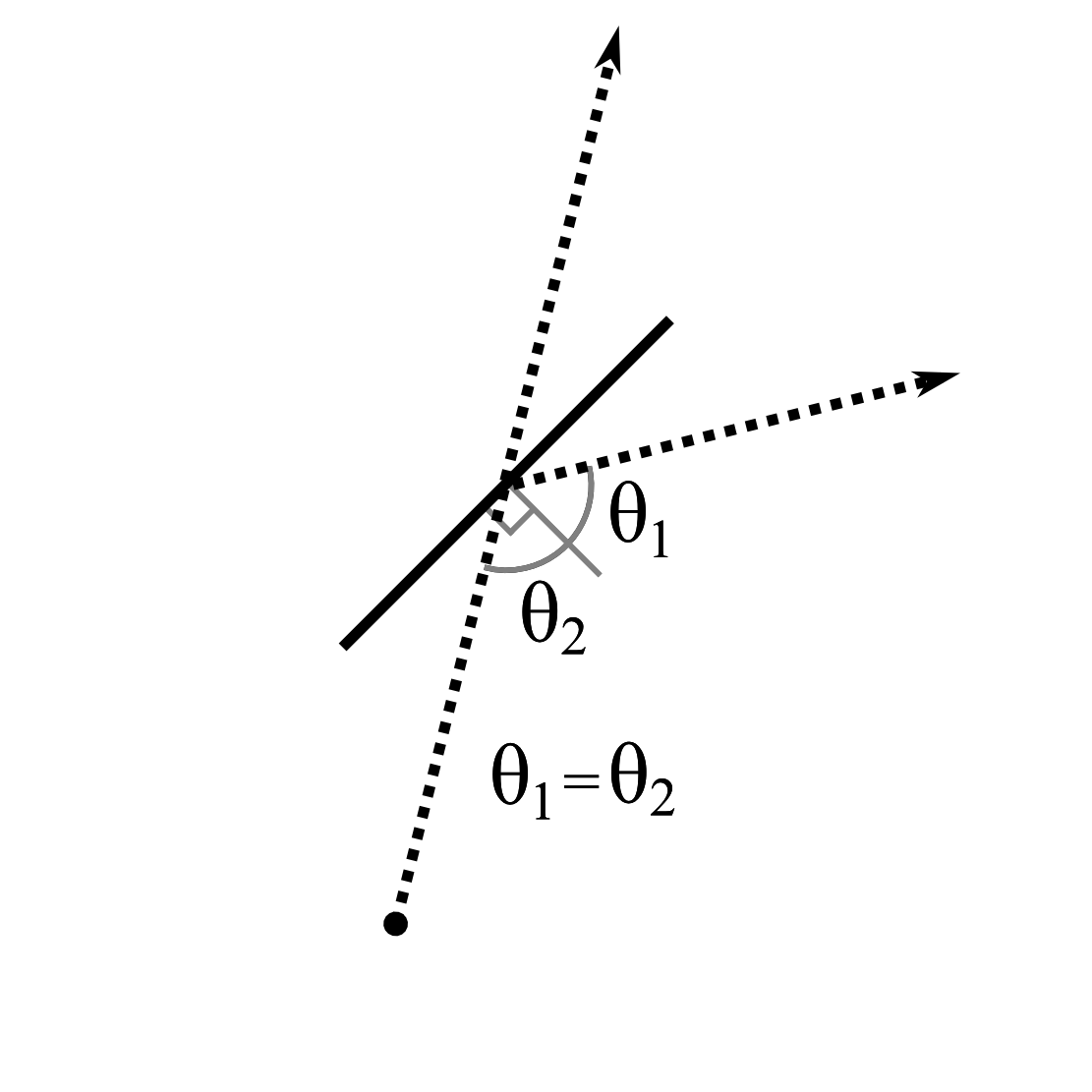
splitter : When a laser beam strikes a splitter, it divides into two beams. One of the new beams will reflect from the splitter surface (as with a mirror), and the other beam will pass through the splitter without changing direction. A splitter will function the same way regardless which side of it is struck by a laser beam.
See the figures below for examples of a laser beam's interaction with each of the possible object types:
|
|
|
| Mirror Object | Splitter Object | Detector Object |
For each simulation, a single laser beam enters the tabletop area. The program must compute the path taken by the laser beam (including secondary beams due to splitters), and it must determine which detectors are struck by a laser beam.
You can make the following assumptions in the program:
- The tabletop surface is a 100 by 100 square, and unless otherwise specified all coordinates in the program's input are given as integers within the tabletop area (i.e. between 0 and 100 inclusive).
- There will be no overlaps between the line segment objects.
- The laser which enters the tabletop area always starts from the edge of the table.
- The simulation of each data set ends when all laser beams have either exited the table top area or have terminated at a detector.
- For each data set there will be no more than 100 total reflections among all laser beams in that data set.
- A laser beam will never intersect any object on a vertex and will never be collinear with an object's line segment.
- Each data set will contain at least one detector object.
Input:
Input to this problem will begin with a line containing a single integer N (1 ≤ N ≤ 100) indicating the number of data sets. Each data set consists of the following components:
- A single line with four numbers "x,y i,j" where x,y is a point along the table edge at which the laser beam enters, and i,j is a vector with integer components (−1024 ≤ i,j ≤ 1024) specifying the direction of the incoming laser beam, where i corresponds to the x-axis direction and j corresponds to the y-axis direction.
- A line with a single integer P (1 ≤ P ≤ 100) giving the total number of objects in this data set.
- A series of P lines, each representing one object, with the first line describing object 1, the second line describing object 2, and so on. Each line begins with a single letter specifying the object type where a "M" indicates a mirror object, "S" a splitter, and "D" a detector. This is followed by two coordinate pairs of the form "x,y", specifying the two end points of the object's line segment.
Output:
For each data set in the input, output the heading "DATA SET #k" where k is 1 for the first data set, 2 for the second, etc. If in this data set none of the detector objects are struck by any laser beams, output the message "NO BEAMS DETECTED". Otherwise, output the object number, one per line, of each detector struck by a laser beam. The list of detectors should be sorted by their object numbers and output in ascending order. If a detector is struck by more than one laser beam, it should only be listed once in the output.
Sample Input:
1
50,100 0,-1
6
D 0,40 20,20
M 40,20 60,40
D 80,20 100,40
D 0,70 20,90
S 40,90 60,70
D 80,90 100,70
Sample Output:
DATA SET #1
1
6

